CaMnO₃ Thin Films: Tuning Electrical Transport with Oxygen
I grew perovskite oxide thin films by pulsed laser deposition and tested how oxygen pressure and fluorination change their structure and resistance.
Lucas Chiang 0 views

The problem
Calcium manganese oxide (CaMnO₃, or CMO) is a perovskite oxide being studied as a catalyst for turning biofuel into diesel, a photocatalyst for splitting water, a fuel cell electrode and a thermoelectric material. What makes it useful in all of these is oxygen: fully oxygenated CMO is an insulator, but removing some oxygen (CaMnO₃₋ᵧ) mixes Mn³⁺ and Mn⁴⁺ ions, and electrons can hop between them, so the resistance drops.
Earlier work in the lab found that CMO films grown at 80 mTorr on LaAlO₃ get less resistive as they get thinner, because strain from the substrate creates oxygen vacancies. My project asked: how do the oxygen pressure during growth and a fluorination treatment change the film's structure and resistance?
What I built
A set of CaMnO₃ epitaxial thin films on LaAlO₃ substrates, each grown under a different oxygen environment, plus a fluorinated version of one film to compare against:
- CMOLAO 067: 80 mTorr oxygen
- CMOLAO 068: vacuum
- CMOLAO 069: 1 mTorr
- CMOLAO 070: 10 mTorr
- CMOLAO 067 fluorinated (SCF), with an as-grown sample and a control
I measured every sample's crystal structure with X-ray diffraction and its resistance with two-probe measurements, then compared how growth conditions changed both.
How it works
Pulsed laser deposition (PLD)
A laser pulses onto a solid CMO target inside a vacuum chamber. Each pulse blasts off a plume of material that lands on a heated single-crystal substrate and builds the film layer by layer. We controlled the oxygen pressure, the pulse energy and the number of pulses.
Fluorination
I mixed 18.7% PVDF (polyvinylidene fluoride) with 81.3% DMF (dimethylformamide), spin-coated one drop onto the 067 film, and left it in the furnace overnight so fluorine could work into the film.
X-ray diffraction (XRD)
X-rays reflect off the planes of atoms, and they only add up into a peak at angles where Bragg's law holds (nλ = 2d sin θ). Comparing the 002 and 202 peaks tells you the spacing of the crystal lattice, so you can see how growth conditions stretch or squeeze the film.
Resistance
Two-probe measurements on every sample, done in an ISO 7 clean room environment.
Gallery
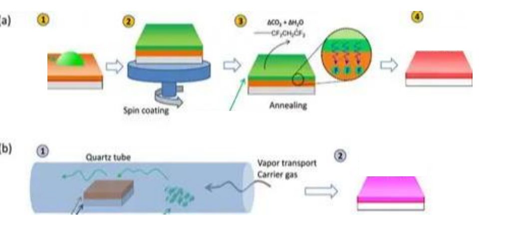
cmo fluorination process 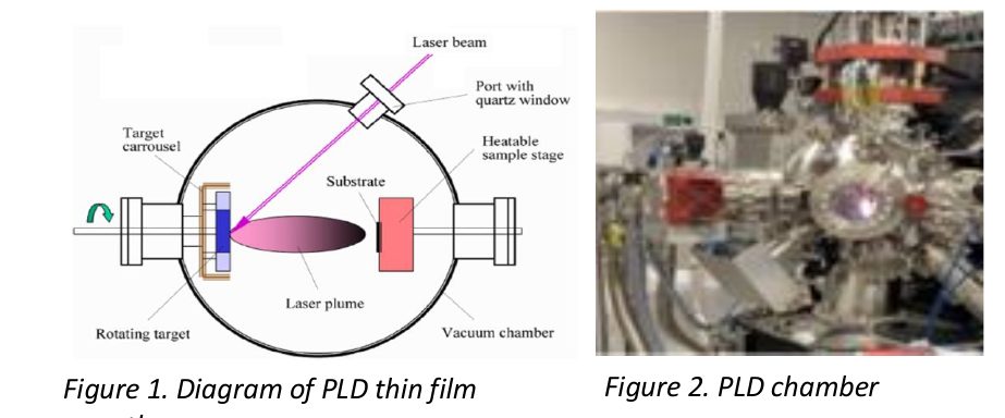
cmo pld chamber 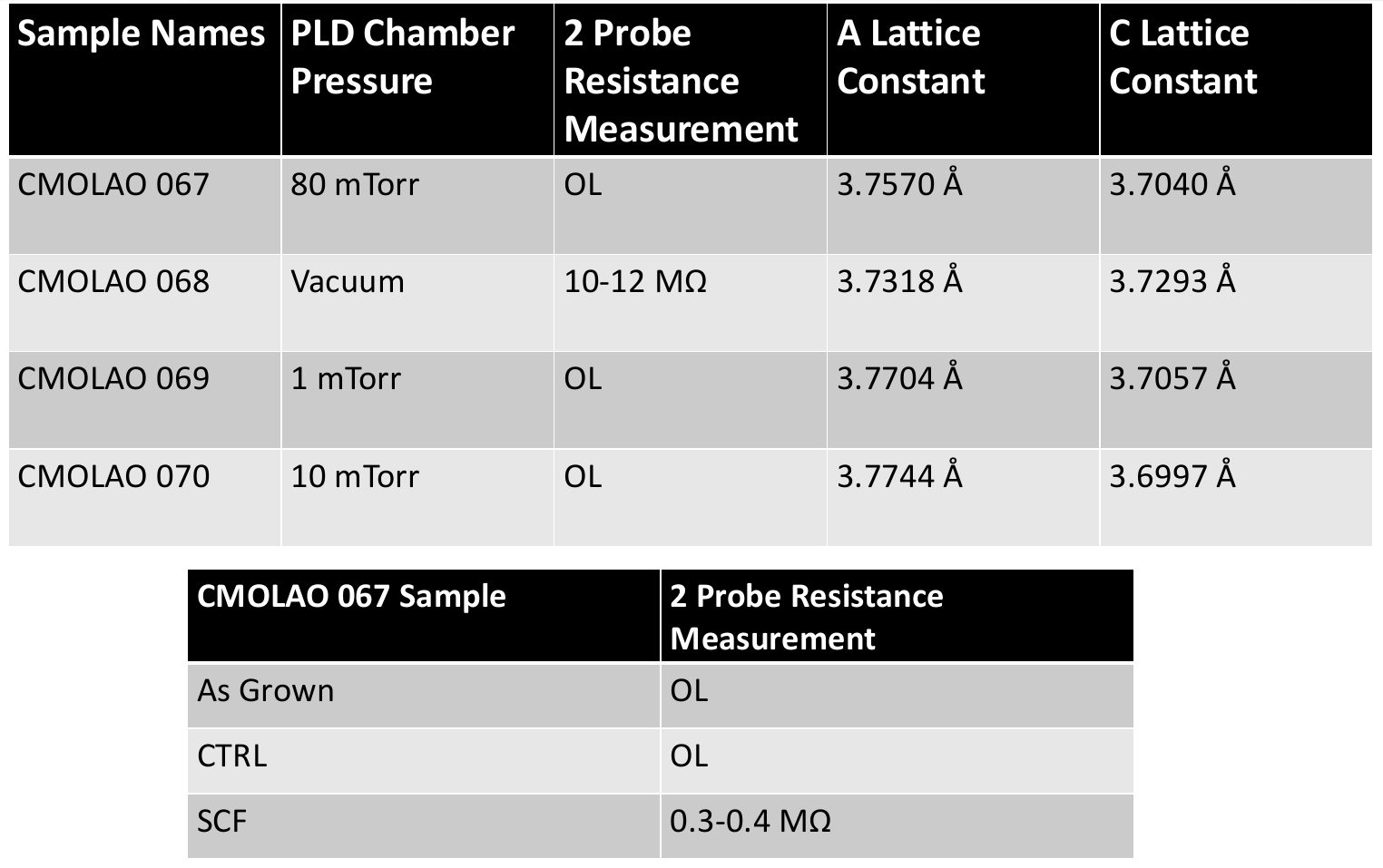
cmo results table 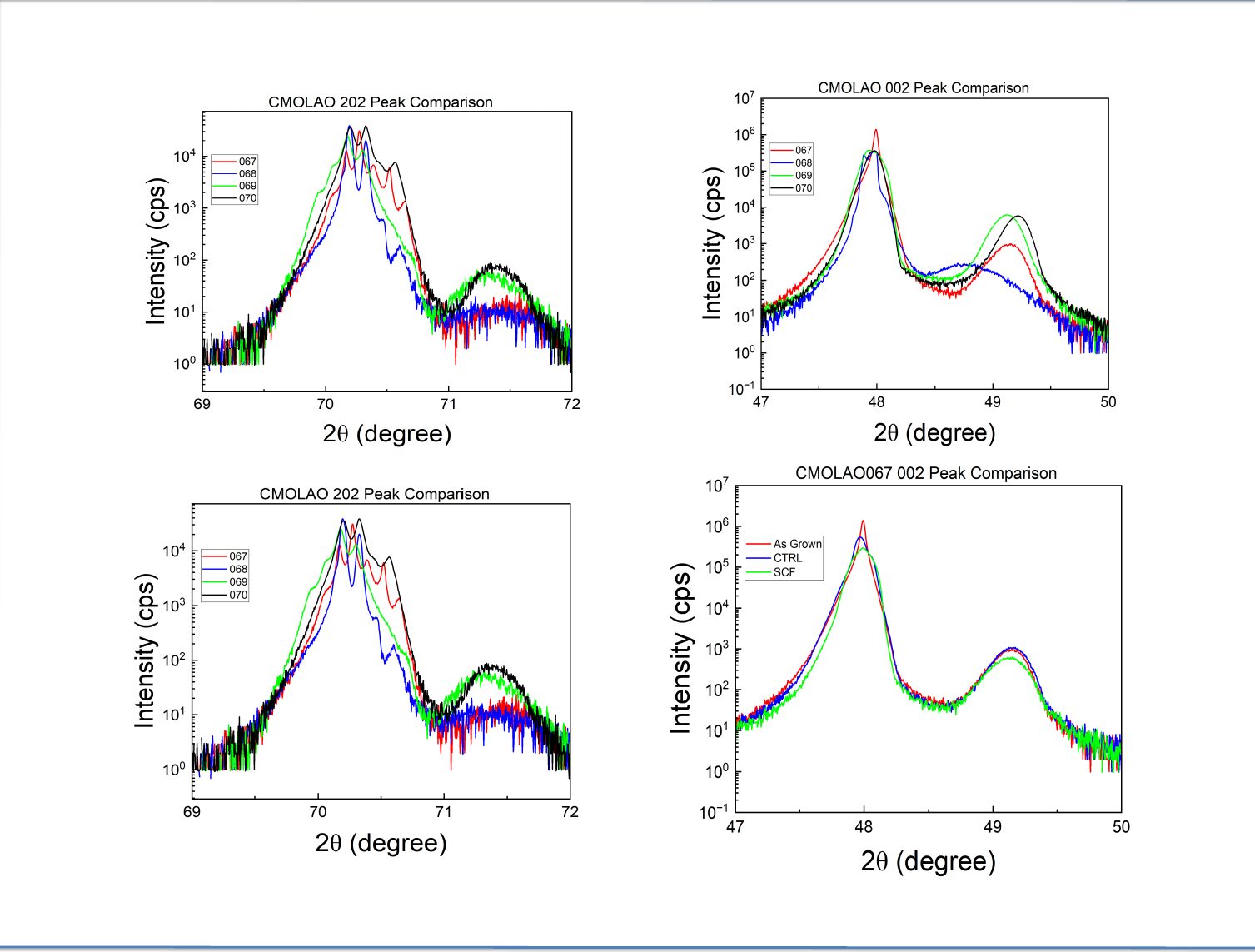
cmo xrd results 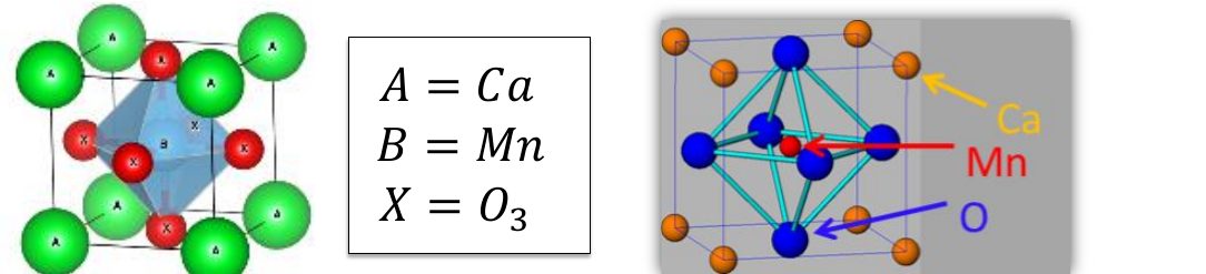
cmo perovskite structure
Results
Four CMO films grown on LaAlO₃ at different oxygen pressures:
CMOLAO 067 · 80 mTorr · resistance OL · a = 3.757 Å · c = 3.704 Å
CMOLAO 068 · vacuum · resistance 10–12 MΩ · a = 3.732 Å · c = 3.729 Å
CMOLAO 069 · 1 mTorr · resistance OL · a = 3.770 Å · c = 3.706 Å
CMOLAO 070 · 10 mTorr · resistance OL · a = 3.774 Å · c = 3.700 Å
Fluorinating film 067 took its resistance from OL (out of range) to 0.3–0.4 MΩ.
Presented as a research poster at Towson University, summer 2025.
What I learned
- Oxygen pressure during growth really does change the film. The vacuum-grown film (068) was the only as-grown sample with a measurable resistance (10–12 MΩ); the others read out of range (OL). It also had a larger c-lattice constant (3.729 Å vs. about 3.70 Å for the others), which fits with more oxygen vacancies.
- Fluorination lowered the resistance of the 067 film from out-of-range to 0.3–0.4 MΩ, and its 002 XRD peak shifted slightly lower than the as-grown and control samples.
- 067 (80 mTorr) and 068 (vacuum) gave more outlier results than 069 and 070, which behaved alike. That matches their growth conditions, which were the two extremes.
- Hands-on lab skills: PLD, spin coating, XRD analysis, resistance measurements and clean room practice, and how to connect a structural measurement to an electrical one.
What I'd improve next
- Fluorinate the 068, 069 and 070 films too and compare their XRD results
- Use four-probe measurements, which take the contact resistance out of the reading, for more accurate resistance values
- Vary film thickness and substrate as well, to separate strain effects from oxygen effects
Discussion (0)
Sign in to join the discussion.